Use a shift register to turn three pins into eight (or more!) outputs!
An integrated circuit ("IC"), or "chip", is a self-contained
circuit built into a small plastic package. (If you look closely
at your Arduino board you'll see a number of ICs.) There are
thousands of different types of ICs available that you can use
to perform many useful functions.
The **74HC595** shift register in your kit is an IC that has eight
digital outputs. To use these outputs, we'll use a new interface
called SPI (Serial Peripheral Interface). It's like the TX and
RX you're used to, but has an additional "clock" line that
controls the speed of the data transfer. Many parts use SPI
for communications, so the Arduino offers simple commands called
shiftIn() and shiftOut() to access these parts.
This IC lets you use three digital pins on your Arduino to
control eight digital outputs on the chip. And if you need
even more outputs, you can daisy-chain multiple shift registers
together, allowing an almost unlimited number of outputs from
the same three Arduino pins! See the shift register datasheet
for details:
[http://www.sparkfun.com/datasheets/IC/SN74HC595.pdf](http://www.sparkfun.com/datasheets/IC/SN74HC595.pdf)
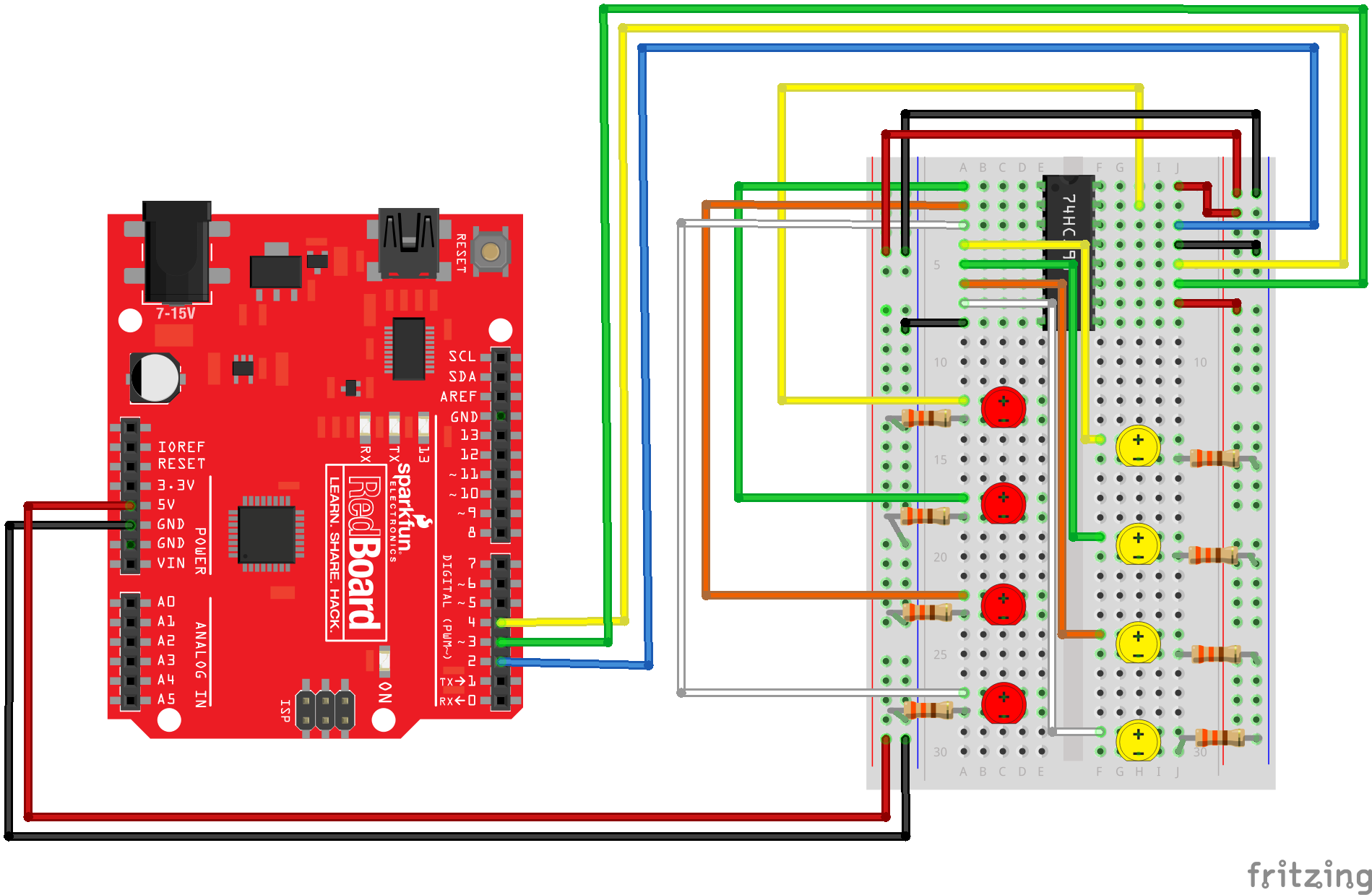
###Hardware connections:
####Shift register:
Plug in the chip so it bridges the center "canyon" on the breadboard.
The shift register has 16 pins. They are numbered counterclockwise starting at the pin 1 mark (notch in the end of the chip). See the datasheet above for a diagram.
74HC595 pin LED pin / Arduino pin
1 (QB) LED 2 +
2 (QC) LED 3 +
3 (QD) LED 4 +
4 (QE) LED 5 +
5 (QF) LED 6 +
6 (QG) LED 7 +
7 (QH) LED 8 +
8 (GND) GND
9 (QH*) No Connection
10 (SRCLR*) 5V
11 (SRCLK) Arduino Digital 3
12 (RCLK) Arduino Digital 4
13 (OE*) GND
14 (SER) Arduino Digital 2
15 (QA) LED 1 +
16 (VCC) 5V
####LEDs:
After making the above connections to the positive (longer)
legs of the LEDs, connect the negative side (short lead) of
each LED to a 330 Ohm resistor, and connect the other side
of each resistor to GND.
Embed This Sketch
Use the following HTML code to embed the sketch code above in your blog or website.
<iframe style="height: 510px; width: 100%; margin: 10px 0 10px;" allowTransparency="true" src="https://codebender.cc/embed/sketch:400589" frameborder="0"></iframe>
Embed The Serial Monitor
You can also embed the Serial Monitor section! Just use this HTML code.
<iframe style="height: 510px; width: 100%; margin: 10px 0 10px;" allowTransparency="true" src="https://codebender.cc/embed/serialmonitor" frameborder="0"></iframe>
